3-Wire Dash Cam A Pillar Airbag Wire Routing Diagram: 2026 Setup
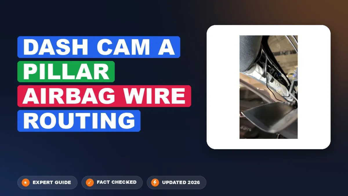
Route the 3-wire harness behind the side curtain airbag canister against the vehicle chassis sheet metal, securing with zip ties to factory harness clips. Connect the yellow hot wire to constant 12V battery power, red to switched accessory power, and black ground wire to an unpainted chassis bolt, keeping deployment paths completely unobstructed.
📌 Key Takeaways
- Always route the harness behind the rolled side curtain airbag canister against the steel pillar to avoid lethal deployment interference.
- Yellow wire supplies constant battery 12V (BATT+), red wire supplies switched accessory 12V (ACC), and black wire attaches directly to chassis ground.
- Use 2A to 5A add-a-circuit fuse taps matched to vehicle-specific mini, micro2, or low-profile fuse slots.
- Zip-tie the hardwire cable directly to OEM wiring harnesses every 4 to 6 inches along the structural frame.
- Seek professional installation if the A-pillar uses non-reusable tether clips or if curtain airbag inflator gas lines block access.
Integrating an aftermarket dash camera into modern vehicle architectures demands rigorous mechanical and electrical tradecraft. Modern passenger vehicles and commercial fleets feature side curtain airbags engineered to deploy from the roof rail and down the A-pillar in milliseconds. Executing professional dash cam a pillar airbag wire routing requires complete separation between the low-voltage power harness and the Supplemental Restraint System (SRS) pyrotechnic deploy path. Careless routing turns shielded conductors into high-velocity projectiles or tethers the curtain envelope during deployment. This comprehensive installation manual details proper A-pillar cable pathways, hardwire kit pin assignments, wire color codes, terminal identification, and secure chassis fastening protocols according to OEM electrical and restraint standards.
Curtain Airbag Mechanics and Safe Dash Cam A Pillar Airbag Wire Routing

Side curtain airbags form an integral barrier designed to shield passenger heads during side-impact (FMVSS 214) and rollover (FMVSS 226) events. The Supplemental Restraint System (SRS) utilizes a cold-gas or pyrotechnic inflator typically mounted along the upper roof c-pillar or directly within the A-pillar cavity. Upon collision sensor triggering, the restraint control module sends an ignition voltage pulse, deploying the folded nylon curtain within 20 to 30 milliseconds at velocities exceeding 140 miles per hour. The deploying cushion breaks the A-pillar interior trim panel away from the steel frame, held captive only by engineered two-stage retaining safety clips.
A frequent error among aftermarket installers is forcing the dash cam power cable into the gap between the door weatherstripping and the A-pillar plastic trim without disassembling the assembly. When a technician pushes a cable along the weatherstrip, the wire spans the gap directly across the airbag deployment plane. If the airbag deploys, this bridged cable acts as a mechanical choke, either preventing full cushion unrolling or snapping the copper conductor and converting the dash cam into a violent cabin projectile. Research into deployment kinetics proves that low-voltage accessories must always be routed behind the airbag cushion envelope, hugging the steel frame of the vehicle A-pillar.
Safe installation protocols require removing the interior trim entirely to expose the factory wiring loom. OEM harnesses traveling up the A-pillar to supply power to the rearview mirror, overhead console, and roof illumination are secured flush against the structural sheet metal, safely separated from the deployment pocket. Anchoring your dash cam power cable to this preexisting factory wiring loom with automotive-grade fasteners ensures that the harness remains inert during an SRS event.
Never route secondary wiring over the face or across the folded envelope of a side curtain airbag module. Always disconnect vehicle battery terminals and allow internal SRS power-reserve capacitors to discharge before servicing components around restraint modules.
| Routing Strategy | Airbag Envelope Relationship | Deployment Dynamics | OEM SRS Compliance |
|---|---|---|---|
| Weatherstrip Gap Tuck | Spans across the unrolling curtain cushion | Airbag snags wire; incomplete inflation or wire tears free | Non-compliant; hazardous installation defect |
| Front Face of Trim | Trapped between garnish and inflator body | Pinched under deployment force; potential short circuit | Non-compliant; high risk of harness severing |
| Chassis/Factory Loom Path | Routed behind cushion assembly against sheet metal | Curtain deploys outward freely; zero interference | Compliant; preserves factory restraint performance |
When running cables downward toward the bulkhead, maintain minimum clearances of at least 15 millimeters from pyrotechnic gas discharge tubes. Adhering to the factory branch locations ensures that the dynamic tear seams molded into the A-pillar trim panel split open as engineered by vehicle safety teams, guiding the fabric downward along the window glass.
Hardwire Kit Wire Color Code, Pin Assignment, and Operating Voltage

Integrating a dash camera system for continuous surveillance requires a hardwire kit with low-voltage cutoff capabilities. Most professional dash cam units rely on a three-conductor harness to distinguish between vehicle running states and stationary surveillance parking modes. Automotive direct current (DC) installations rely on clear polarity standards: unlike alternating current (AC) equipment featuring a live hot wire, neutral wire, and earth ground, 12V/24V vehicle electronics implement a battery constant feed, a switched ignition accessory feed, and a negative chassis ground return path.
Standard hardwire kits convert 12.0V–24.0V DC vehicle operating voltage to regulated 5.0V DC output via an inline buck converter. Conductors should measure between 20 AWG and 24 AWG tinned copper wire, rated for engine and interior temperature ranges from -40°C to +85°C.
The constant battery feed (labeled B+, BAT, or Direct-Wire) provides continuous operating current to memory buffers and internal radar/G-sensors during parking surveillance. The switched accessory circuit (labeled ACC or IGN) delivers a voltage signal only when the ignition cylinder or accessory relay is energized, signaling the camera to switch from low-power parking standby to full-rate driving capture. The ground wire completes the DC circuit back to the vehicle bare metal chassis. If you are retrofitting hardware powered by a dedicated high-capacity storage buffer, refer to our companion auxiliary battery pack wiring manual for isolated isolation relay schemes.
| Wire Function | Standard Wire Color Code | Fuse Box Connection Point | Pin Assignment (USB-C / Mini-B) | Voltage & Gauge Specs |
|---|---|---|---|---|
| Constant Hot Wire (B+) | Yellow (or Red depending on brand) | Hazard lights, Door lock module, Horn | Pin 1 (Mini-B VBUS) / Pin A4/B4, A9/B9 (USB-C) | 12.0V–24.0V nominal; 22 AWG |
| Switched Ignition (ACC) | Red (or Yellow depending on brand) | Radio, Power outlets (Cigar socket), Wipers | Pin 4 (Mini-B Sense via resistor) / Pin A5/B5 (CC) | 12.0V–14.4V switched; 22 AWG |
| Chassis Ground Wire (GND) | Black | Structural bare-metal chassis bolt / Nut | Pin 5 (Mini-B GND) / Pin A1/B1, A12/B12 (USB-C) | 0.0V Ground Reference; 20–22 AWG |
| DC Step-Down Output | Black Molded Outer Sheath | Dash Cam Power Port (Direct Input) | VBUS (+5V) and GND (Ground) terminal pins | 5.0V DC regulated; 1.5A to 3.0A output |
Always inspect the manufacturer labeling printed on the buck converter casing. While Japanese and Korean dash cam systems (such as Thinkware and BlackVue) predominantly adopt Yellow for Battery Constant and Red for Switched Accessory, several commercial fleet platforms invert these identifiers (Red for Constant, Yellow for Switched). Connecting the constant hot wire to a switched circuit will disable parking impact detection, whereas terminating the switched lead to a continuous power line prevents the camera from recognizing engine shutdown, inducing premature vehicle battery drain.
Low-voltage cutoffs built into these harnesses monitor supply voltage at the interior vehicle fuse box terminal block. For standard 12V flooded, EFB, or AGM batteries, configure the cutoff switches to 12.0V or 12.2V under moderate temperatures, and 12.4V in freezing winter environments. Commercial 24-volt systems require setting the cutoff threshold to 24.0V minimum to prevent low-voltage starting failures on heavy equipment.
Step-by-Step Dash Cam A Pillar Airbag Wire Routing Installation Protocol
Performing correct dash cam a pillar airbag wire routing demands methodical disassembly, clean cable drops, and mechanical containment. Follow this chronological protocol to integrate your dash cam power cable without compromising active vehicle safety systems.
For detailed vehicle-specific electrical source selections across foreign and domestic fuse banks, consult our in-depth fuse tap installation guide before cutting or crimping auxiliary leads.
-
De-Energize the Vehicle Electrical and SRS System
Turn the vehicle ignition to the complete OFF position and remove the key or smart fob outside transmission range. Disconnect the negative (black) battery terminal from the vehicle battery using an insulated 10mm wrench. Secure the disconnected terminal away from the post. Wait a minimum of 15 minutes before proceeding; this latency period allows the internal backup capacitors of the Supplemental Restraint System (SRS) diagnostic module to discharge completely, eliminating unintentional pyrotechnic deployment hazards. -
Peel Door Weatherstripping and Garnish Trim
Open the passenger door fully. Firmly grasp the dynamic rubber door weatherstripping mounted to the door frame body pinch weld adjacent to the A-pillar. Pull the weatherseal inward and downward until the metal pinch seam and the outer edge of the A-pillar interior trim panel are fully revealed from the roofline down to the dashboard sill. -
Disengage the A-Pillar Interior Trim Panel
Insert a broad-blade nylon trim removal pry tool between the plastic A-pillar trim and the structural sheet metal pillar at the top edge nearest the headliner. Apply gentle outward leverage until the primary spring retaining safety clip pops free. Note that many modern vehicles (including Toyota, Honda, BMW, and Ford architectures) employ a captive two-stage green or orange plastic tether clip engineered to catch the trim during airbag expansion. Do not pry violently against this captive clip. Insert long-reach needle-nose pliers or a dedicated clip-release tool, rotate the tether clip 90 degrees (or depress the release tabs on both sides), and disengage it from the metal chassis slot. Pull the garnish upward out of the dashboard integration tabs and remove it from the vehicle. -
Mount Dash Cam and Route Along Headliner
Position the dash cam on the windshield behind or adjacent to the rearview mirror housing, ensuring the lens sweeps through the cleared path of the windshield wipers. Run the dash cam power cable upward, tucking it behind the front lip of the headliner using a non-marring tool. Continue routing horizontally inside the front perimeter of the headliner toward the top of the disassembled passenger-side A-pillar. -
Bridge the Headliner-to-Pillar Transition Behind the Airbag
At the transition junction where the headliner meets the upper A-pillar structure, locate the rolled side curtain airbag module. Under no circumstance should the wire cross in front of the rolled cushion. Route the dash cam wire behind the structural mounting bracket of the airbag, guiding the lead directly against the vehicle sheet metal where factory wire looms enter the roof channel. -
Anchor Cable to the Factory Wiring Loom
Trace the OEM factory wiring loom traveling downward along the steel A-pillar structure. Lay the dash cam power cable flat alongside this factory harness. Using industrial automotive fleece tape (such as Tesa 51608) or miniature nylon UV-resistant zip ties spaced at 100mm intervals, secure the dash cam cable to the factory loom. Trim all zip tie tails flush using micro-flush cutters to eliminate sharp edges that could abrade nylon airbag fabrics under chassis vibration. -
Pass Through the Instrument Panel Bulkhead
Route the lower terminal drop of the dash cam power cable down into the interior dash structure through the lower access opening between the base of the A-pillar frame and the dashboard end cap. Ensure the wire does not rub against the sharp stamped edges of the steel cross-car dashboard reinforcement beam. Pull the harness downward until it reaches the interior vehicle fuse box cavity. -
Terminate Hot Wire, Switched Accessory, and Ground Wire
Identify unswitched and switched fuse slots using a calibrated digital multimeter on the terminal block bus bars. Crimp matching add-a-circuit fuse taps to the continuous hot wire (B+) and the switched accessory wire (ACC). Insert the fuse taps into their corresponding slots, seating original fuses in the lower bridge and accessory fuses (2A to 5A) in the upper tap channel. Terminate the black negative ground wire ring terminal onto an unpainted, structural steel factory ground bolt, torquing the chassis bolt to OEM specification (typically 9 to 12 Nm for an M6 fastener). If troubleshooting cabin entry for external auxiliary cameras, see our OBD-II power harness routing guide for alternate lower-dash power pickup options. -
Inspect Clearances and Reassemble Trim Components
Inspect the entire length of the routed cable to confirm zero tension, excess slack, or physical impingement on the folded airbag cushion. If the two-stage retaining safety clip was stretched, distorted, or fractured during extraction, discard it and install an OEM replacement clip immediately to maintain crash safety compliance. Align the lower trim locator pins into the dashboard base, push the A-pillar garnish firmly inward until the metal and plastic retaining clips seat flush with a solid click, and reseat the door weatherstripping over the trim edge. Reconnect the battery negative terminal, start the vehicle, and verify normal dash cam function and absence of SRS warning lights on the instrument cluster.
Dash Cam A Pillar Airbag Wire Routing Pitfalls, Noise, and Rattle Mitigation
Executing an installation that is functionally sound in static conditions is only half the battle. Technicians must anticipate dynamic mechanical forces, thermal expansion cycles, and crash deployment realities. Overlooking harness securing protocols leads to catastrophic restraint system failures or annoying interior noise, vibration, and harshness (NVH) issues.
- Crossing Over the Airbag Deployment Envelope: The most dangerous mistake during dash cam a pillar airbag wire routing is laying the harness across the front face of the side curtain airbag module. In a side-impact collision, the inflating gas bag will pull the wire taut across the cabin, snapping the copper strands, ripping the camera off the glass, and transforming it into an unguided projectile traveling at head-level. Always route conductors down the frame side, strictly behind the curtain envelope.
- Reusing Fatigued Retaining Safety Clips: OEM manufacturers design A-pillar trim tether clips with specific shear and expansion rates. If a two-stage clip is warped, stressed, or snapped during removal, the A-pillar interior trim panel will not release correctly during an airbag deployment or could detach into the cabin. Always inspect plastic clips for stress blushes (whitened plastic) and replace them with OEM factory clips (e.g., Honda Part #91561-TA0-A01, Ford Part #W714972-S300, or Toyota Part #62217-52120).
- Failing to Mitigate Interior Buzz, Squeak, and Rattle (BSR): Bare PVC or polyurethane-jacketed cables routed inside the metal A-pillar will slap against the bare chassis sheet metal or hard plastic trim under regular driving vibrations. This produces persistent buzzing and clicking inside the cabin. Wrap the entire length of the drop cable traversing the pillar in poly-PET fleece electrical harness tape (e.g., Tesa 51608). The high-damping non-woven fleece cushions the wire against vibration impacts, suppressing cabin noise.
- Pinching Wires During Garnish Re-engagement: When snapping the A-pillar garnish back onto the steel chassis, loose cable slack can wander directly between the perimeter locator pins or metal retention clips and their sheet metal mounting holes. Forcing the trim inward pinches the power wire against the sharp sheet metal stamped edge, compromising the insulation sleeve and generating an intermittent dead-short that will blow the auxiliary fuse or damage the buck converter.
- Inadequate Chassis Grounding and High Resistance: Securing the negative ground wire ring terminal to an interior trim screw mounted into an unthreaded stamped sheet metal bracket introduces high contact resistance. Painted, clear-coated, or anodized mounting locations degrade the ground path, causing sudden power interruptions, erratic parking mode drops, and image sensor corruption due to electrical ground looping. Always use an established OEM chassis ground wire stud featuring zinc-plated hardware welded to the main unibody shell.
- Leaving Loose Cable Bunches Near Lower Airbag Anchors: Leaving coiled dash cam power cable loops stuffed carelessly into the bottom of the A-pillar cavity can foul the curtain airbag bottom anchoring tethers. If the bottom tether cannot snap taut during inflation, the lower edge of the curtain will flutter loose, reducing occupant ejection mitigation capabilities. Bundle all excess wire length flat at the fuse box cavity using heavy-duty zip ties anchored cleanly to structural dash framing.
Dash Cam A Pillar Airbag Wire Routing Technical Inquiries
Can you tuck the dash cam cable along the door weatherstripping without removing the A-pillar trim?
No. Tucking an accessory power wire into the exterior seam between the door weatherstripping and the A-pillar garnish without disassembling the pillar crosses the deployment envelope of modern curtain airbags. When tucked into the rubber gasket, the wire physically bridges the opening through which the airbag emerges to protect the occupant's head. During an impact, the deploying airbag will either be restrained by the tensile strength of the copper harness or snap the wire, ejecting the camera into the passenger compartment. Proper trim removal and mechanical routing behind the airbag assembly along the factory wiring loom is mandatory for occupant safety.
What wire gauge is required when extending a 12V-to-5V dash cam power cable?
If you must extend the DC input leads (the 12V/24V constant hot wire, switched accessory wire, or ground wire prior to the buck converter), use standard 18 AWG to 22 AWG automotive stranded copper wire (SAE J1128 Type TXL or GXL). If extending the low-voltage 5V output lead after the buck converter down to the camera connector, the wire size must be heavier (minimum 20 AWG) to counteract severe voltage drop. Running standard 26 AWG or 28 AWG consumer USB wiring over runs longer than 3 meters can cause the 5.0V regulated line to dip below 4.65V under high processing loads (such as Wi-Fi transferring or rear camera channel encoding), resulting in boot-looping and SD card write failures.
Why does the side curtain airbag retaining safety clip have a two-stage release mechanism?
The A-pillar interior trim panel is designed to separate partially—roughly 20mm to 35mm—away from the metal A-pillar during curtain deployment, creating a designated ejection gap for the nylon cushion while preventing the heavy plastic garnish panel from flying off into the passenger cabin. Automotive engineers achieve this via captive, two-stage tether clips. When servicing the A-pillar for wiring installation, technicians must release the tether mechanism rather than ripping the trim forcefully outward. Straining or fracturing the two-stage clip destroys its mechanical tethering function, requiring complete replacement before reinstallation.
How does a three-wire hardwire kit detect parking mode transition without vehicle data network access?
A standard three-wire dash cam power harness does not connect to the vehicle CAN-bus network or communicate digitally with powertrain ECUs. Instead, the onboard internal micro-controller inside the hardwire buck converter monitors the physical voltage state across the red switched accessory (ACC) input pin. When the vehicle ignition is running, the ACC line supplies full system voltage (12.6V–14.4V). When the driver shuts off the engine, the ACC circuit drops to 0.0V. The internal converter circuitry senses this differential voltage state immediately and transmits a discrete trigger pulse down the Mini-USB or USB-C identification pin (Pin 4 on Mini-USB or Pin A5/CC on USB-C), prompting the dash camera operating firmware to transition into parking standby mode.
Which factory ground wire attachment points are safe for dash cam chassis grounding?
Safe ground terminations must be secured directly to unpainted, factory-welded unibody steel using existing structural ground bolts or dedicated ground studs identifiable by existing OEM brown or black ground harnesses. Never use cosmetic sheet metal dash framing screws, loose plastic clip wells, steering column brackets subjected to rotational wear, or airbag inflator module mounting hardware. Fastening a dash cam ground wire to an airbag mounting bracket can introduce electrical noise into restraint trigger circuitry or interfere with factory module fault detection diagnostics. Clean, factory-torqued chassis grounding studs ensure solid ground continuity with measured electrical resistance below 0.1 Ohms back to the negative battery terminal.
Dash Cam a Pillar Airbag Wire Routing: Frequently Asked Questions
What wire color is constant power on dash cam a pillar airbag wire routing?
In standard 3-wire hardwire kits, the yellow lead represents the constant hot wire (BATT+), which maintains parking surveillance mode. The red lead serves as the switched accessory trigger (ACC), while the black lead functions as the chassis ground wire returning current to the vehicle frame.
What do the pin assignments mean on dash cam a pillar airbag wire routing kits?
The 3-pin assignment on the voltage converter module maps to Battery Constant (Pin 1), Switched ACC Ignition (Pin 2), and Ground Return (Pin 3). At the camera end, standard Type-C or Mini-USB pinouts supply 5V DC step-down power and trigger parking surveillance switching based on input voltage states.
How many wires does dash cam a pillar airbag wire routing have?
Most parking-mode hardwire harnesses utilize three distinct conductors: a 12V constant hot wire, a 12V switched ignition line, and an earth ground wire. Standard plug-and-play auxiliary USB cables require only two conductors (positive 5V and ground return), which do not support low-voltage battery cutoff parking modes.
What are common wiring mistakes with dash cam a pillar airbag wire routing?
The most dangerous mistake is bridging the wire directly across the face of the airbag cylinder, turning the cable into a high-speed projectile during deployment. Other frequent errors include reversing the ACC and hot wire leads, relying on painted ground bolts, and omitting inline fuses.
Do I need a fuse tap for dash cam a pillar airbag wire routing?
Yes, dual-slot add-a-circuit fuse taps provide critical electrical isolation without cutting factory harness lines. Always install the factory vehicle fuse in the bottom slot and the supplied 2A to 5A dash cam fuse in the top tap slot to maintain independent overcurrent protection for both systems.
What gauge wire does dash cam a pillar airbag wire routing require?
Hardwire kits typically utilize 20 AWG to 24 AWG copper strand wire for the 12V primary run, terminating at an internal 12V-to-5V step-down regulator. This light gauge easily clears tight A-pillar weatherstripping while safely handling the 1.5A to 2.5A operating draw of high-resolution dual-channel dash cameras.