
Dash Cam Ground Point Best Step-by-Step Guide 2026
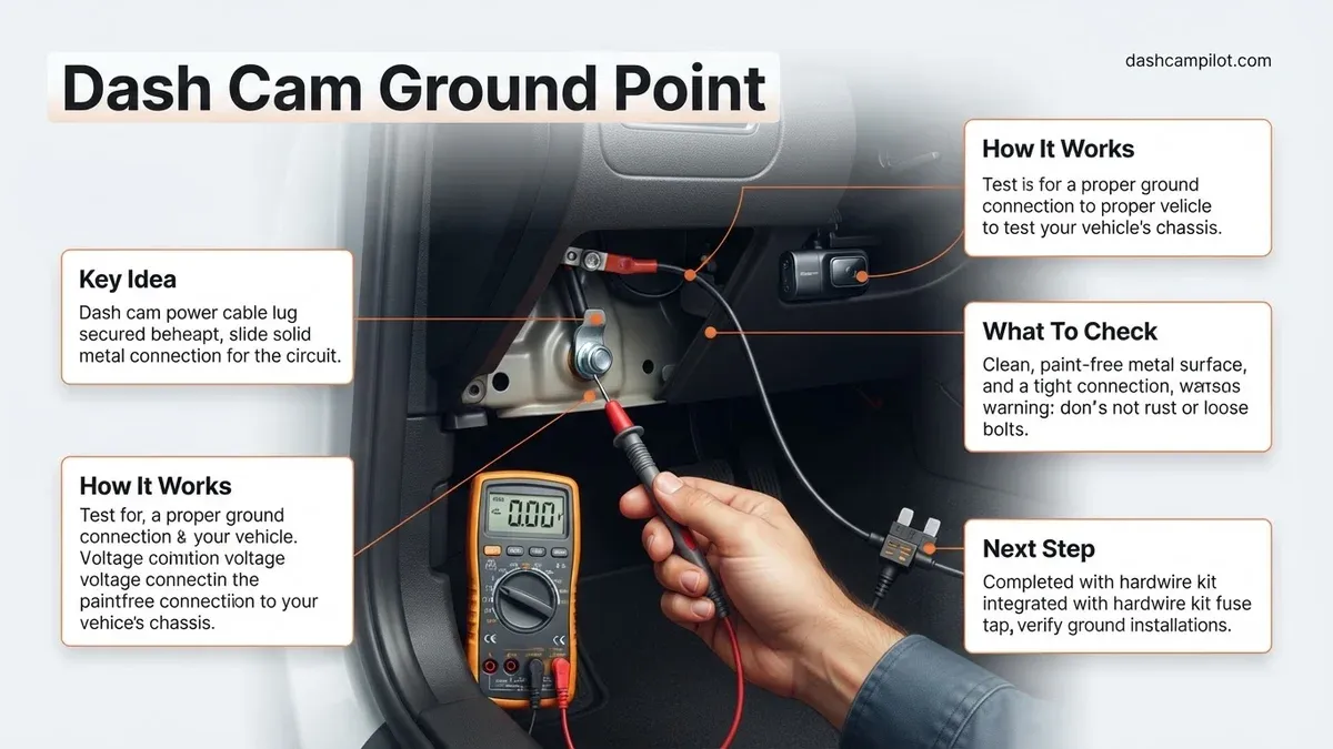
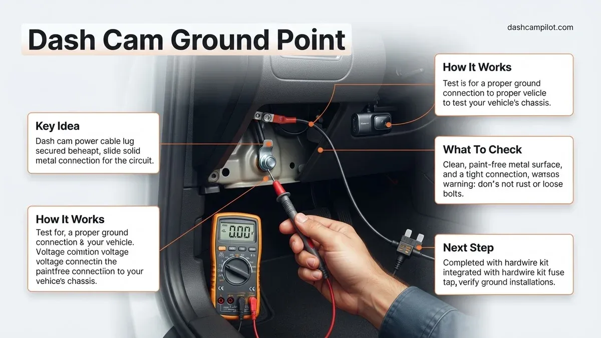
A reliable dash cam ground point must connect directly to bare, unpainted vehicle chassis metal to complete the electrical circuit properly. Grounding to painted metal, plastic trim, or loose brackets causes intermittent reboot loops and power loss. Selecting an unpainted factory chassis bolt near your interior fuse box guarantees stable power delivery.
The ideal ground point for hardwiring your dash cam is an unpainted, metal-to-metal factory bolt screwed directly into your vehicle’s steel chassis, typically within 12 to 18 inches of the interior fuse box. Connecting your black wire to this point completes the circuit, allowing direct current to return safely to the battery. Without this path, your hardwire kit cannot supply steady voltage to the camera.
Getting this ground connection wrong causes the vast majority of hardwiring problems in 2026 vehicles. Sensitive body control modules and sophisticated battery-monitoring systems will interpret a poor ground as an electrical fault. This results in random camera reboots, failed parking mode activation, and corrupted video files. Securing a reliable bare-metal contact eliminates these headaches before you tuck a single wire into your trim.
Key Takeaways
- Attach the ground ring terminal to bare, unpainted structural chassis metal near the fuse box.
- Never connect the ground wire to painted hardware, plastic subframes, or airbag mounting bolts.
- Test continuity with a digital multimeter to confirm zero resistance to the car chassis.
- Sandwich the terminal directly between the vehicle frame and the factory bolt washer.
- Tighten the bolt firmly to prevent vehicle vibrations from loosening the electrical contact.
What Causes Dash Cam Grounding Failures: Painted Metal and Loose Contacts
Most failed hardwire installations trace back to high electrical resistance at the ground terminal. Even if a bolt looks securely fastened, invisible barriers often disrupt the flow of current. Your dash cam kit needs less than 0.5 ohms of resistance to run reliably, and modern automotive assembly methods make finding that low resistance trickier than it used to be.

The Hidden Insulator: Automotive Paint and E-Coating
Modern vehicle frames undergo an electro-deposition coating (e-coat) process during manufacturing. This creates a remarkably durable, corrosion-resistant primer over every square inch of sheet metal. Unfortunately, e-coat and standard automotive clear coats are non-conductive electrical insulators.
When you slip a ground fork or ring terminal under an uncleaned painted bolt head, metal rarely touches metal. Current must fight through the coating, creating a severe voltage drop under load. As soon as your dash cam boots up or switches to parking mode, the circuit sags and the camera cuts out.
False Grounds and Plastic Retention Clips
Modern car interiors rely heavily on composite materials, acoustic dampeners, and isolated sub-assemblies. Just because a fastener has a metal hex head does not mean it connects to the vehicle's electrical ground. Common false grounds include:
- Trim Retaining Bolts: Screws holding dash trim or kick panels frequently thread into nylon inserts or plastic anchor clips rather than metal.
- Isolated Bracket Bolts: Metal braces behind the knee airbag or glove box often sit on rubber isolation bushings, completely breaking electrical continuity with the chassis.
- Painted Structural Fasteners: Fasteners dipped in black oxide or coated with thread-locking compound resist current, even when driven into bare steel.
How to Identify a Proper Dash Cam Ground Point Near the Fuse Box
Finding a dependable ground requires checking the vehicle's structural skeleton rather than decorative or support brackets. You need an unpainted, solid steel or aluminum junction tied directly to the unibody.
Spotting Factory Ground Lugs
Automakers already run dedicated ground stations near major junction points. To locate one, inspect the area within 12 inches of your cabin fuse panel—usually found in the driver-side kick panel, behind the lower dash bolster, or near the base of the A-pillar.
Look for a cluster of brown (common in European models) or black/white-striped (common in Japanese and domestic models) wires converging onto a single chassis bolt. These factory ground points connect directly to bare, unpainted unibody metal. Tapping into one of these existing anchor points is the cleanest, most reliable way to ground your camera.
Testing Ground Continuity with a Multimeter
Never guess whether a bolt is grounded; test it. A budget digital multimeter set to measure resistance takes seconds and guarantees success:
- Set your multimeter to the lowest resistance setting (typically 200 ohms) or the audible continuity mode.
- Place the black probe onto a known bare metal ground, such as an unpainted door striker pin, a bare hinge bolt, or the negative battery terminal post if accessible.
- Touch the red probe firmly to your candidate bolt head or unpainted chassis frame.
- Read the display: a reliable ground point will show less than 0.2 ohms (or trigger a steady continuity tone).
- If the display shows high resistance (above 1.0 ohm) or reads "OL" (open loop), that bolt is isolated and will cause camera malfunction.
If you must use a structural bolt that has paint underneath its head, you must prep the surface first. Use a brass wire brush, a rotary tool, or 120-grit sandpaper to remove the factory primer directly beneath the bolt washer. Exposing a nickel-sized patch of shiny, raw sheet metal ensures clean conductivity without sacrificing structural integrity.
How to Install and Secure the Ground Wire: Step-by-Step DIY Fix
Proper mechanical bonding guarantees that the dash cam hardwire kit functions without voltage drops. Electrical engineers specify that ground connections must maintain direct metal-to-metal continuity without intermediate non-conductive barriers.
Preparing the Grounding Terminal
- Inspect the terminal lug: Ensure the factory ring or spade terminal on the black ground wire is securely crimped using an automotive-grade ratcheting crimper. Loose crimps introduce resistance and cause intermittent reboots.
- Select the unpainted chassis bolt: Choose an unpainted factory bolt threaded directly into the chassis frame near the interior fuse panel. Avoid screws that anchor into plastic brackets or structural clips.
- Loosen the bolt: Use a metric socket wrench (typically 8mm, 10mm, or 12mm) to back out the fastener completely.
Securing and Torquing the Connection
- Clear surface coatings: Scrape away any paint, clear coat, or surface oxidation using 120-grit sandpaper or a wire brush until bare, shiny steel or aluminum is exposed.
- Seat the terminal flush: Place the ring terminal directly against the bare chassis metal. Place any factory ground wires or washers on top of the dash cam terminal, not beneath it.
- Torque the fastener: Tighten the chassis bolt to automotive specifications, typically between 7 and 9 lb-ft (9.5 to 12 Nm) for standard M6 hardware. This prevents thermal loosening from daily road vibrations.
What If It Still Doesn't Work? Ground Troubleshooting and Fallbacks
If the dash cam fails to power on after tightening the ground screw, systematic testing isolates whether the issue is a high-resistance ground, an open circuit, or a bad hot lead.
Advanced Diagnostic and Fallback Steps
- Perform a continuity test with a digital multimeter: Switch the meter to the lowest Ohms (Ω) setting. Place one probe on the ground terminal and the other on a known unpainted frame point. A functional ground must read under 0.2 ohms; readings above 0.5 ohms indicate insufficient contact.
- Relocate to the A-pillar structural weld nut: Some inner dash braces use adhesive bonding rather than spot welds, isolating them electrically. Move the ground wire to an A-pillar factory grounding point or an unpainted kick-panel structural bolt.
- Confirm fuse tap orientation: Verify that the add-a-fuse tap is not inserted backward in the fuse slot. Modern 2026 hardwire kits require both the battery/ACC power leads and ground to be closed circuits before the buck converter activates.
- Test with an external jumper wire: Attach a temporary jumper wire from the dash cam ground lead directly to the negative battery terminal or door striker pin. If the dash cam instantly boots, the original grounding bolt is defective.
- Consult a certified professional: If grounding fails to restore power, modern EV electrical architectures or CAN bus sleep monitors may be blocking auxiliary 12V circuits. Seek a Mobile Electronics Certified Professional (MECP). In 2026, professional diagnostic rates for automotive electrical labor average between $95 and $150 per hour.
Conclusion
A failed dash cam installation usually traces back to high ground impedance rather than a dead camera. By securing the black ground lead directly against bare chassis metal and validating continuity with a multimeter, drivers eliminate reboot loops and protect parking-mode functionality. Before reassembling interior trim panels, run a final ignition test to confirm the unit sleeps and wakes reliably. According to verified research and expert sources across automotive electronics standards, maintaining a low-resistance ground return remains the single most critical factor for auxiliary vehicle safety hardware reliability.
❓ Frequently Asked Questions
Where is the most common dash cam ground point located?
The most common location is inside the driver-side or passenger-side kick panel directly beside the interior fuse box. Vehicle manufacturers place multiple unpainted steel chassis bolts and existing wiring harness ground clusters in this area for convenient access.
What should I do if the bolt metal is covered in factory paint?
If unpainted metal is unavailable, use fine-grit sandpaper or a wire brush to gently scrape away a small circle of paint beneath the bolt head. Exposing the raw, shiny bare steel ensures the terminal makes full contact with the chassis.
Why does my dash cam restart continuously when the car is running?
A floating or weak ground connection is the leading cause of constant dash cam reboot loops. Vehicle vibrations cause loose or high-resistance ground terminals to intermittently lose connection, instantly resetting the camera.
Does the size of the ground terminal ring matter?
Yes, using an oversized ring terminal can lead to poor surface contact, while an undersized C-clamp will not slide over the bolt thread. If necessary, crimp a properly sized 8mm or 10mm ring terminal onto the black ground wire for a snug fit.
Can I use a self-tapping screw into bare sheet metal as a ground?
While technically functional, self-tapping screws are prone to loosening over time from road vibration and can induce corrosion. It is strongly recommended to use existing factory structural metric bolts already welded into the frame.
How can I verify my ground is good without a multimeter?
Connect an automotive 12V test light's clip to a confirmed 12V positive fuse slot and touch the probe tip to your selected ground bolt. If the test light illuminates brightly, the ground point is conducting properly.